
A 60kW rating alone doesn’t show whether a storage inverter will suit your site. The IESP 60kW storage inverter has a rated output of 60,000 W in a three-phase configuration, and its fit depends on how battery current and solar inputs align with your loads and storage design.
This guide explains how battery charging and discharging, MPPT inputs, conversion efficiency and three-phase output affect hybrid solar storage, then outlines what to consider when matching the inverter with batteries, solar generation and facility demand.
Key Takeaways
- Assess battery charging and discharging current against the storage bank and the site’s operating demands.
- Match three-phase output voltage and rated power to the facility’s electrical requirements.
- Use MPPT input limits and conversion efficiency to evaluate how the inverter fits the solar array design.
- Plan hybrid operation around solar generation, battery storage and site loads, including whether parallel units suit the system.
Battery charge and discharge current
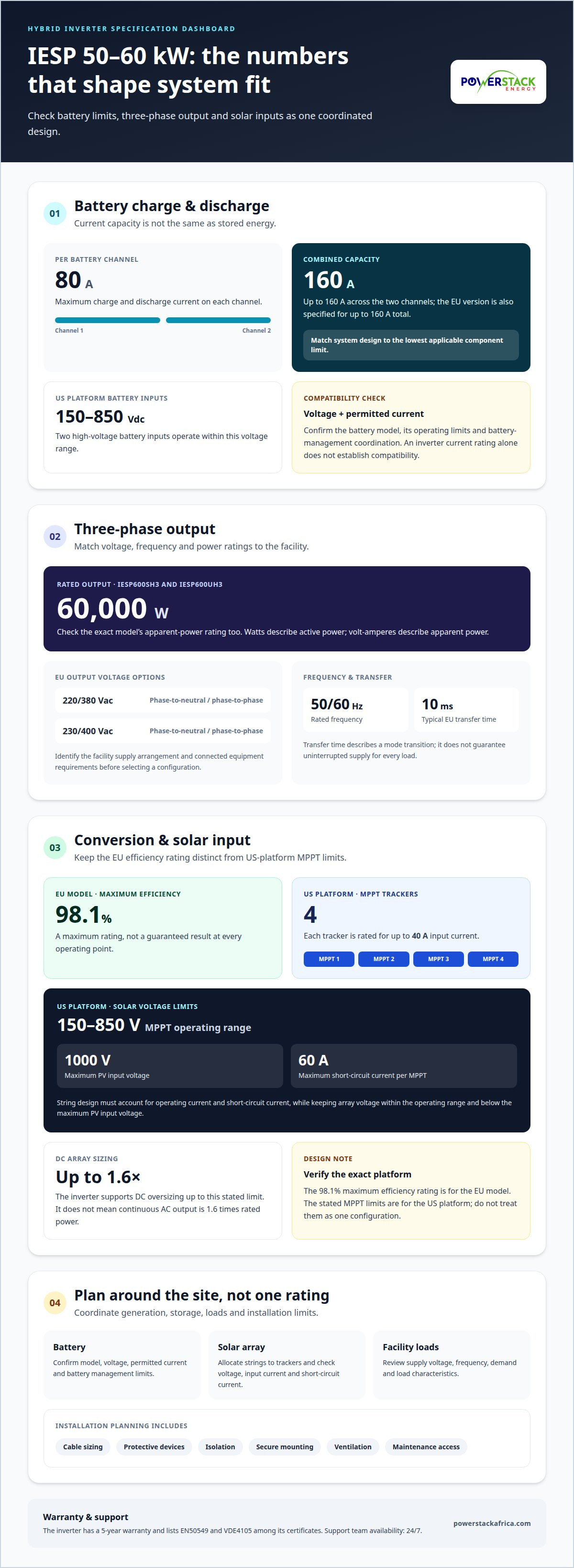
The SRNE IESP 50~60kW inverter supports a maximum battery charge and discharge current of 80A on each of two channels. Together, those channels provide up to 160A. The EU version is also specified for up to 160A total. These ratings describe current capacity, not stored energy. Battery capacity and inverter current therefore answer different design questions.
For the US platform, two high-voltage battery inputs operate across 150-850Vdc. That range determines which battery voltage configurations can connect within the platform’s operating limits. With high-voltage lithium storage, the battery management system and inverter must coordinate charge and discharge limits. The battery’s voltage and permitted current both matter; a high current rating alone doesn’t establish compatibility.
In practice, the available battery current affects how quickly storage can charge from solar or supply loads. The site’s load profile, battery limits and inverter channel capacity shape that operation. A battery energy storage system should be designed around the lowest applicable limit across its connected components. This helps prevent the inverter’s 160A capacity from being mistaken for the battery’s own rating.
For warranty and support in Kenya, the inverter has a 5-year warranty and lists EN50549 and VDE4105 among its certificates. The company’s support team is available 24/7; warranty terms and support are distinct.
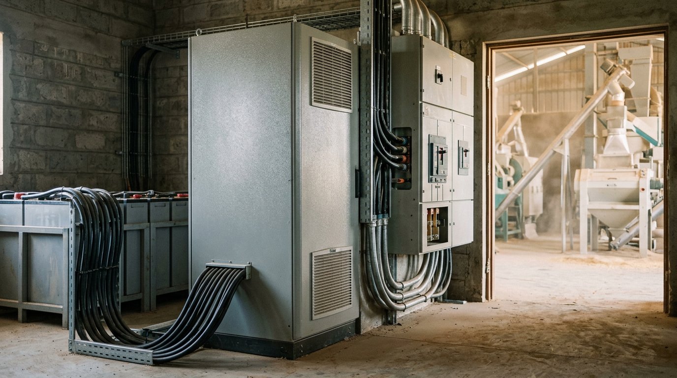
Installation planning starts with the site, battery and wiring. The design must account for the inverter’s high-voltage battery range, the selected battery’s limits, suitable cable sizing, protective devices, isolation and secure mounting. Site access, ventilation and the route between the inverter, battery and distribution equipment also shape the layout. Together, these factors support safe connections and practical maintenance access.
Before installation, establish the battery model and its operating limits, then match the wiring and protection to the design current. Confirm that the chosen battery input stays within 150-850Vdc on the US platform. Treat the two battery channels and their 80A ratings as design limits, not as a substitute for system-level engineering.
Three-phase output voltage and rated power
Match the inverter’s three-phase output to the site supply and connected loads. Check voltage, frequency and power ratings to confirm compatibility.
Three-Phase Voltage Options
The SRNE IESP 50-60kW EU inverter supports 220/380Vac and 230/400Vac output options. These are phase-to-neutral and phase-to-phase voltage pairs, respectively. Identify the facility’s supply arrangement and equipment requirements before selecting an output configuration. A voltage mismatch can prevent correct integration with distribution equipment or connected loads. Include the required voltage in the system design.
Rated and Maximum Output Power
The IESP600SH3 and IESP600UH3 each have a rated output power of 60000W. Apparent power ratings can vary between inverter models, so check the specification for the exact model. Watts describe active power; volt-amperes describe apparent power. Compare both ratings with facility demand, especially where loads have different power factors.
Frequency is rated at 50/60Hz, while the EU inverter’s typical transfer time is 10ms. Frequency must align with the connected electrical system. Transfer time describes the transition between operating modes, not a guarantee that every load experiences uninterrupted supply. Include both figures in the design review, alongside the site’s load characteristics.
For grid-connected overload operation, distinguish rated output from temporary overload capability. The figures above specify rated power and maximum apparent power, not an overload duration or percentage. Grid export limits and facility demand also affect operation. Assess the inverter’s rating against the intended operating mode instead of treating apparent power as additional continuous output.
In Kenya, plan the grid connection around the applicable utility interconnection process and electrical safety requirements. Include the site’s connection arrangement, inverter output voltage and intended operating mode in that review. Complete the required approvals and safety checks before commissioning. The specific steps depend on the installation’s grid interface.
Conversion and MPPT efficiency
The SRNE IESP 50-60kW EU inverter has a maximum efficiency rating of 98.1%. This figure describes maximum conversion efficiency, not a guaranteed result at every operating point. Actual energy conversion varies with conditions such as input power and load. For system planning, treat the rating as a benchmark, then consider how the inverter will operate alongside the solar array, battery and facility demand.
MPPT, or maximum power point tracking, adjusts the solar input operating point to capture available panel power. The US platform has an MPPT operating range of 150-850V and four MPPTs, each rated for up to 40A input current. Its maximum PV input voltage is 1000V. These figures define separate design limits: operating voltage, absolute input voltage and current per tracker.
Each tracker’s limits matter when arranging solar strings. The US platform also rates its MPPTs at up to 60A short-circuit current each. String design must account for both operating current and short-circuit current, rather than relying only on the 40A input rating. Keep the array’s voltage within the MPPT range during operation, while ensuring it does not exceed the 1000V maximum PV input voltage.
The SRNE IESP 50~60kW inverter supports DC oversizing up to 1.6 times. This allows the connected PV array’s rated DC capacity to exceed the inverter’s AC rating within that stated limit. It does not mean the inverter can continuously output 1.6 times its rated power. Array sizing should consider the site’s generation profile, tracker allocation and inverter output capacity together.
Use the specifications as a coordinated set: the 98.1% maximum efficiency rating belongs to the EU model, while the stated MPPT voltage and current limits describe the US platform. Don’t combine those figures as if they describe one configuration. Confirm the exact platform in the design documentation, then match the solar string layout to its voltage, current and tracker limits.
Three-phase hybrid solar storage
A three-phase hybrid system coordinates solar generation, battery storage and facility loads. Its suitability depends on the operating mode, load balance and expansion requirements.
Hybrid Solar Storage Configuration
In a hybrid configuration, solar power can serve site loads while storage supports energy use when generation changes. The system design must coordinate the inverter, battery and three-phase distribution. For sites with uneven phase demand, the US platform supports 100% unbalanced loads. That capability can help address phase imbalance, but load distribution still informs the system design.
The EU inverter supports parallel operation of 1-9 units. This gives system designers an option to expand inverter capacity through parallel units, subject to the system design and operating requirements. Consider whether one inverter meets the facility’s demand or whether parallel operation better fits a planned expansion.
Comparison with Other Hybrid Inverters
Compare the IESP platform with other 60kW hybrid inverters by checking output configuration, battery limits, PV input specifications, efficiency and parallel operation. Available figures show the EU model’s 1-9-unit parallel capability and the US platform’s 100% unbalanced-load support. These specifications enable a criteria-based comparison, but don’t establish that one inverter is better across every site.
For a fair comparison, use the same operating context: three-phase loads, solar array design, battery voltage and facility demand. Then assess each platform’s specifications individually, without combining EU and US figures.
Key risks include mismatched battery or PV limits, uneven phase loading and operating conditions that affect inverter output. The 50~60kW inverter’s stated temperature range is -40 to +60°C, with derating above 45°C. Maintenance planning should account for the installation environment, equipment condition and operating records. Inspect connections, ventilation paths and system alerts as part of planned maintenance, following the applicable equipment guidance.
The practical takeaway: base hybrid design on the site’s load profile and the exact inverter platform. Discuss your three-phase storage design to align operating requirements with system configuration.
Powerstack Africa Energy: Hybrid Inverters & PCS
Powerstack Africa Energy supports businesses assessing a three-phase storage project through its Hybrid Inverters & PCS offering. Its portfolio includes the IESP 60kW HV C&I Storage Inverter, alongside Battery Energy Storage Systems and Commercial Solar EPC. These offerings are relevant when you need to align inverter selection with solar generation, battery storage and facility requirements.
To evaluate a project, define the site’s load profile, battery configuration, solar array and intended grid-connected or hybrid operation. These inputs help shape an integrated system design and clarify the inverter’s role. Powerstack Africa Energy provides Commercial Solar EPC alongside battery storage and power conversion solutions to support this work.
Contact Powerstack Africa Energy to discuss your three-phase solar storage requirements.
Turn the inverter choice into a project plan
Start by defining what the system must support over its operating life. Map current facility demand, planned load changes and the role storage should play in daily operations. This gives your project team a basis for assessing system configuration and integration needs, rather than treating inverter selection as an isolated equipment decision.
For a site considering an IESP 60kW storage inverter, Powerstack Africa Energy Ltd can connect the equipment decision with its wider project scope. Its Commercial Solar EPC, Battery Energy Storage Systems, and Hybrid Inverters & PCS offerings support planning across generation, storage, and power conversion. The team’s engineering experience can help translate site requirements into a practical project design.
Bring your facility requirements and intended operating priorities into the discussion. Contact Powerstack Africa Energy Ltd to discuss your project and identify a suitable next step. A clear design brief is a sound starting point for a well-planned energy system.
Frequently Asked Questions
What is the IESP 60kW storage inverter and what are its specifications?
The IESP 60kW storage inverter is a three-phase hybrid inverter for solar and battery systems. The IESP600SH3 and IESP600UH3 models have 60000W rated output power. EU versions support 220/380Vac or 230/400Vac output and have a maximum efficiency rating of 98.1%. Platform specifications differ, so use the exact model designation when assessing system requirements.
What battery voltage and chemistry are compatible with the IESP 60kW inverter?
The US platform accepts battery inputs across 150-850Vdc and supports up to 160A total charge or discharge current. Voltage compatibility alone doesn’t establish battery chemistry compatibility. For example, a high-voltage lithium battery must also align with the inverter’s battery management and communication requirements. Match the battery’s operating voltage, chemistry, permitted current and control interface to the exact inverter platform.
What are the inverter’s maximum solar PV input voltage, current, and power?
On the US platform, maximum PV input voltage is 1000V, with an MPPT operating range of 150-850V. It has four MPPTs, each rated for up to 40A input current and 60A short-circuit current. The inverter supports DC oversizing up to 1.6 times. Apply these limits to the selected platform and array design; don’t treat the MPPT operating range as the maximum voltage.
Is the IESP 60kW inverter three-phase, and what are its grid and backup output ratings?
Yes, the IESP 60kW models discussed here are three-phase. Rated output power and maximum apparent power are distinct specifications, so check the exact model’s ratings. EU output voltage options are 220/380Vac and 230/400Vac. The EU version has a typical 10ms transfer time; assess grid and backup loads against the specific model’s output ratings.