The largest battery bank is not automatically the right choice for a Kenyan project. High-voltage battery storage in Kenya should be sized around the loads to support, the required backup duration and the potential for expansion. Usable capacity and system compatibility matter as much as the headline rating.
Compare battery format, depth of discharge and cycle life to see how each option fits your operating requirements. This guide explains how to estimate capacity from your loads, compare LiFePO₄ formats and plan a scalable installation, including the role of inverters and power conversion equipment.
Key Takeaways
- Choose a wall-mounted or rack-mounted format based on available space, installation layout and the system’s intended scale.
- Size usable capacity against your priority loads and required backup duration, rather than relying on headline battery capacity alone.
- Compare cycle life alongside depth of discharge to understand how operating patterns affect long-term battery performance.
- Plan for future demand by checking how battery modules, inverters and power conversion equipment work together as the system expands.
Wall-mounted and rack-mounted LiFePO4 batteries
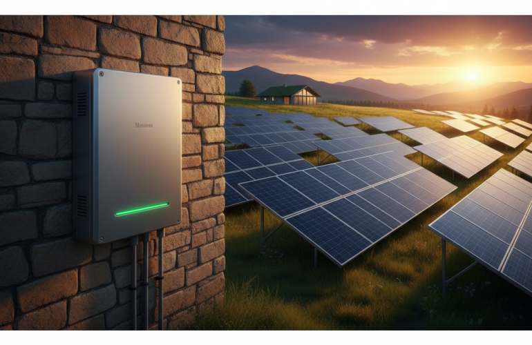
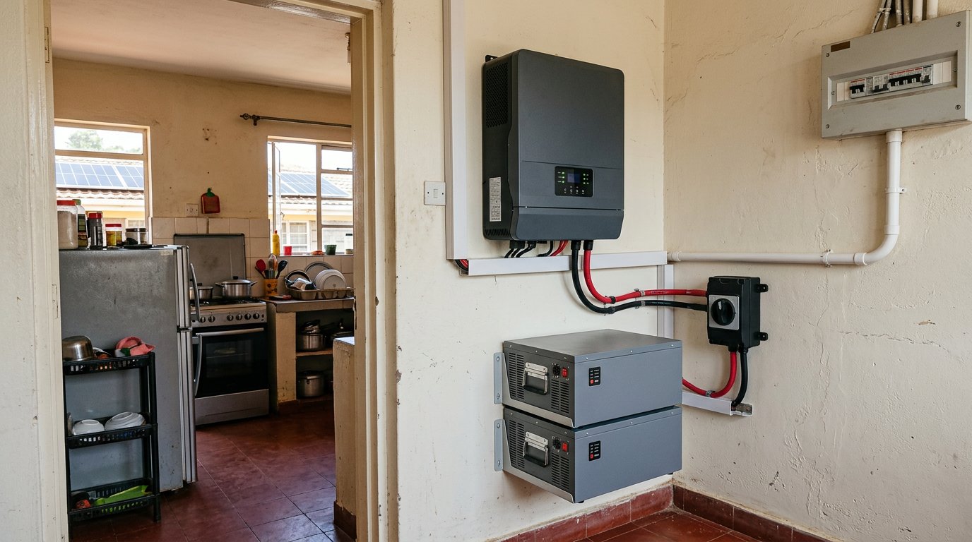
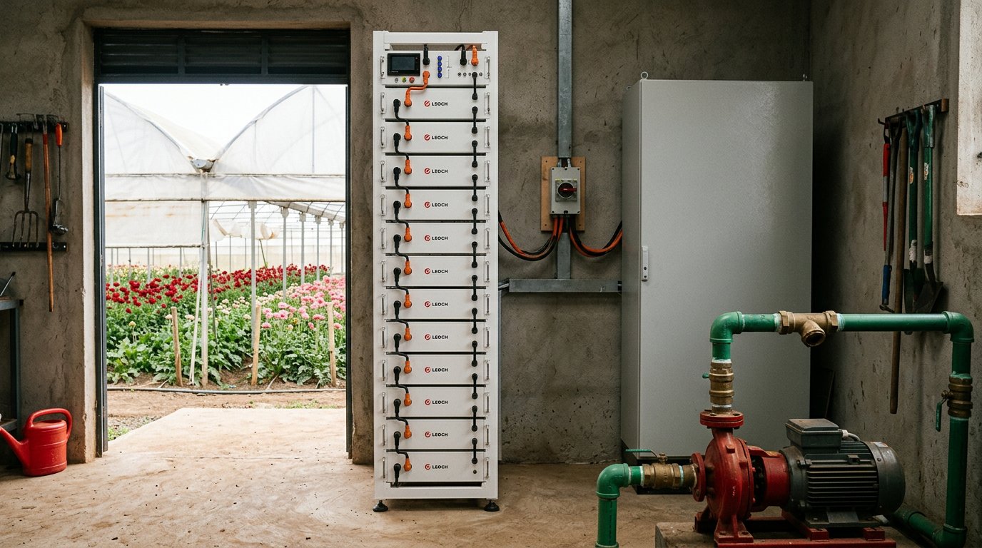
The best high-voltage battery storage systems in Kenya match your load profile, inverter and expansion plan. LiFePO4 battery chemistry uses lithium iron phosphate cells; system selection still depends on usable capacity, control compatibility and installation format. Wall-mounted units suit installations with suitable wall space and manageable access requirements. Rack-mounted modules fit a standing cabinet or equipment room, where technicians can arrange components and service connections. Both formats can support backup and energy storage when correctly designed for the site.
Battery format affects layout, not the basic sizing method. A wall-mounted unit keeps floor space clear, while a rack system groups modular batteries in a designated equipment area. A facility planning staged expansion, for example, may prefer a rack layout if compatible modules can be added later. High- and low-voltage systems differ in operating voltage and current requirements. The right choice depends on capacity, inverter compatibility, installation scope and project scale, so neither voltage class is universally preferable. Efficiency depends on the complete battery-and-inverter design, while safety relies on appropriate protection and installation practices.
Kenyan electrical, safety and import requirements depend on the installation and equipment classification. Project design should account for applicable electrical approvals, fire-safety provisions and import rules, rather than assuming one requirement covers every system. High-voltage batteries can work with solar inverters when their voltage range, communications protocol and control functions are compatible. A qualified design review should assess these interfaces before equipment is selected.
Risk controls include electrical isolation, correctly rated protection, secure mounting and suitable thermal management. Installation and maintenance should follow the equipment maker’s instructions, with trained personnel checking connections, alarms and system operation. Financing, tax treatment and incentives depend on the project structure and applicable Kenyan provisions; financial modeling should compare available financing routes and assess tax and incentive eligibility. For a high-voltage LiFePO4 system, define the load, location, inverter interface and expansion plan before choosing a wall-mounted or rack-mounted solution.
Battery capacities and sizing for Kenyan projects
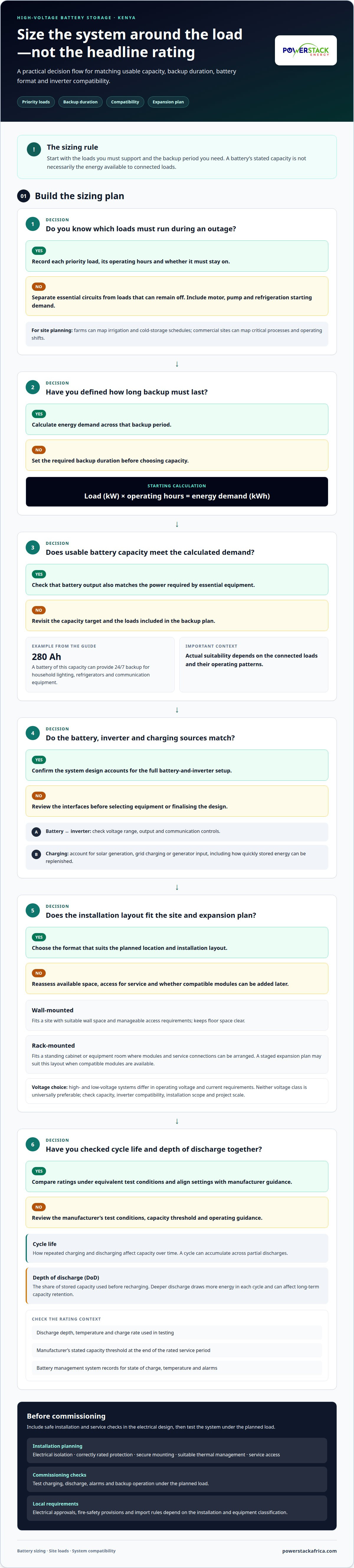
Choose capacity from the energy your priority loads consume and the backup duration you require. A useful starting calculation is load in kilowatts multiplied by operating hours, producing energy demand in kilowatt-hours. For example, a 280 Ah battery can provide 24/7 backup power for household lighting, refrigerators and communication equipment. Actual suitability depends on the loads connected and their operating patterns.
Build your load estimate from equipment schedules, not the combined ratings of every appliance. Separate essential circuits from loads that can remain off during an outage. Include the starting demand of motors, pumps and refrigeration equipment, since their initial draw can exceed normal running demand. For farms, account for irrigation and cold-storage schedules; for commercial sites, map critical processes and operating shifts. This gives your designer a realistic capacity target.
Next, account for usable battery capacity, inverter limits and expected charging sources. A battery’s stated capacity is not necessarily the energy available to connected loads. The design must match battery output to the inverter and the power required by essential equipment. Solar generation, grid charging and generator input also affect how quickly stored energy can be replenished. Product ratings help compare systems, but site conditions determine the right configuration.
Use this sequence to size and plan installation:
- Record each priority load, its operating hours and whether it must run during an outage.
- Calculate energy demand across the required backup period, then account for usable battery capacity.
- Match battery voltage, output and communication controls with the inverter and charging sources.
- Set the installation location, isolation, protection and service access into the electrical design.
- Commission the system by testing charging, discharge, alarms and backup operation under the planned load.
For Kenyan projects, assess outages alongside normal daily consumption. A system designed only around a brief interruption may not meet prolonged backup needs; one sized for every load can add capacity that the operating plan does not require. A battery energy storage design can bring load data, inverter selection and installation requirements into one project specification. Businesses can also explore commercial load shifting solutions to align flexible electricity use with solar generation and manage demand peaks.
Battery cycle life and depth of discharge
For a LiFePO4 battery, cycle life describes how repeated charging and discharging affect capacity over time. A cycle may accumulate across partial discharges, rather than requiring one full discharge. Compare manufacturer cycle-life data only alongside its test conditions, including discharge depth, temperature and charge rate. Those conditions determine whether a published rating reflects your residential use or a business operating profile.
Depth of discharge (DoD) is the share of stored capacity used before recharging. Deeper discharge draws more energy from the battery in each operating cycle and can affect long-term capacity retention. A suitably sized system can limit routine discharge depth while preserving backup energy for priority loads. The appropriate operating target depends on daily consumption, charging opportunities and required backup duration.
- Compare cycle-life ratings under equivalent test conditions, not as isolated headline claims.
- Check the manufacturer’s stated capacity threshold for the end of the rated service period.
- Review whether the battery management system records state of charge, temperature and alarms.
- Align charge and discharge settings with the battery manufacturer’s operating guidance.
LiFePO4 performance also depends on temperature and charging behaviour. Excessive heat can accelerate battery ageing, while unsuitable charging settings can affect safe operation and available capacity. The battery management system helps control cell operation, but correct inverter configuration remains essential. Review system data for changes in state of charge, charging interruptions or recurring alarms.
Efficiency and cycle life are different measures. Round-trip efficiency describes how much energy remains available after charging and discharging losses. Inverter conversion, battery operating limits and system settings all affect the energy delivered. For example, a residential system serving evening loads may cycle differently from a business system supporting daytime equipment and overnight backup.
For stable performance, set operating limits around actual loads, charging patterns and backup priorities. Record battery settings during commissioning, then review system logs during scheduled maintenance. These steps help identify changes early and keep the LiFePO4 battery operating within its intended parameters.
Scalable and stackable battery systems
A scalable design starts with current demand and provides a defined path for future expansion. A household might support essential circuits first, then add storage as consumption changes. At a commercial site, expansion may follow new equipment, longer operating shifts or additional backup needs. In both cases, modular architecture can stage capacity without redesigning the entire energy storage system.
Adding modules does not mean any battery can be connected to an existing bank. Modules must match the system’s voltage, communications and control design. The inverter or power conversion system must also support the planned configuration and charging demand. A sound design identifies which components can expand, what settings may need to change and whether the original equipment can accommodate added capacity.
- Map demand stages: define current priority loads and likely additions, such as a new cold room or pump.
- Set the expansion path: identify compatible battery modules and their required arrangement.
- Review power limits: check that the inverter can manage expected charging and discharge loads.
- Reserve installation space: plan access, mounting and electrical routes for future modules.
- Document commissioning: record system settings and test operation after each expansion.
Plan charging carefully as storage grows. A larger battery bank needs more energy to recharge, so available solar generation, grid supply or generator input must match the intended recovery period. Adding modules without reviewing charging capacity could prevent the expanded system from reaching its operating target as planned. Load forecasting helps align future demand with storage and charging requirements.
For high-voltage battery storage in Kenya, specify the expansion sequence before procurement. Document the initial configuration, compatible additions and inverter limits in the project design. This gives facility teams a practical basis for scheduling capacity changes while preserving clear control and maintenance procedures. Plan a scalable battery storage system around your current loads and future expansion needs.
Powerstack Africa Energy Ltd
Powerstack Africa Energy Ltd helps turn battery requirements into a coordinated energy system for your Kenyan project. Its Energy Audits assess site demand and operating patterns, while Commercial Solar EPC brings project design and implementation together. Battery Energy Storage Systems and Hybrid Inverters & PCS support system integration, with equipment selected to suit the project’s load profile and expansion needs.
This approach is useful when you need to align battery capacity, inverter compatibility, charging sources and future growth in one design. Clear load data and backup priorities help define the project scope and guide technical decisions. Contact Powerstack Africa Energy Ltd to discuss your battery storage project.
Set the next project decision
Turn the storage concept into a project brief based on actual operating priorities. Define which loads must stay online, how the system should work with existing power sources and what future changes it needs to accommodate. This gives the design process a clear basis for technical decisions.
For high-voltage battery storage in Kenya, Powerstack Africa Energy Ltd can bring Commercial Solar EPC, Battery Energy Storage Systems and Hybrid Inverters & PCS together within one project scope. This is relevant when you need storage integrated with a wider solar or power conversion design, rather than treating the battery as a standalone component.
Share your project requirements with Powerstack Africa Energy Ltd to discuss the next design step. Contact Powerstack Africa Energy Ltd and move your storage planning forward with a clear technical brief.
Frequently Asked Questions
What does high-voltage battery storage mean for homes and businesses in Kenya?
A high-voltage battery system stores electricity in a battery bank designed to work with a high-voltage inverter or power conversion system. At home, storage can support selected circuits when grid supply is unavailable. In a business, it can work alongside solar generation, the facility grid or a generator. The system design determines which sources charge the battery and how stored power serves site loads.
What battery capacity and inverter size do Kenyan homes and businesses need?
Capacity and inverter power should match the site’s load profile and the equipment that must operate together. Battery capacity, measured in kilowatt-hours, indicates stored energy; inverter rating, measured in kilowatts, indicates power conversion capability. For example, the SAJ 50 kW All-In-One Energy Storage Solution has a 100 kWh battery and a nominal two-hour energy-to-power ratio at 50 kW, subject to system limits.
Which Kenyan suppliers and installers offer high-voltage battery storage systems?
Powerstack Africa Energy Ltd supplies Battery Energy Storage Systems and integrates Hybrid Inverters & PCS for projects in Kenya. Its listed options include the Dyness STACK100 High Voltage LiFePO₄ Battery Energy Storage System and KET A High Voltage Battery. Commercial Solar EPC and Energy Audits can also support projects that need storage coordinated with solar generation and site energy requirements.
What warranties, lifespan, and performance can buyers expect in Kenya’s climate?
Warranty and performance terms depend on the specific battery model and its manufacturer conditions. The DEYE BOS-W has a 5-year warranty, subject to manufacturer terms; Dyness STACK100 is rated for ≥ 8,000 cycles / 10 years, which is cycle-life information rather than a warranty. Operating limits also vary by model. For DEYE BOS-G Pro, charging is 0 °C–55 °C and discharging is –20 °C–55 °C.